Introduction
Additive manufacturing (AM) has matured beyond rapid prototyping. For engineers, it now offers a legitimate path to production-quality parts—provided designs are tailored to the process. This is where Design for Additive Manufacturing (DfAM) becomes essential.
DfAM isn’t simply a checklist of minimums and maximums; it’s a mindset shift. It’s about understanding how geometry, orientation, and material selection intersect with the realities of AM processes such as FDM, MJF, SLS, and SLA. For polymer-based technologies especially, performance and printability are directly linked to how a part is conceived at the design stage.
Accounting for Directional Strength
One of the defining characteristics of 3D printing is anisotropy. Because parts are built layer by layer, mechanical properties vary by direction. In most processes, the Z-axis—vertical to the build plate—is the weakest point due to inter-layer bonding limitations.
Designers aiming for load-bearing performance must align critical mechanical paths with the X-Y plane. Snap fits, cantilevers, or stress-bearing arms printed upright are far more likely to fail than those oriented for lateral load. Understanding this early helps avoid redesigns and mechanical surprises down the line.
Respecting Process-Specific Wall Thicknesses
Every AM technology imposes constraints on wall thickness. Too thin, and features deform or fail to print. Too thick, and excess thermal mass leads to internal stresses or wasted material. In general, supported FDM parts require at least 0.8 mm of wall thickness, while SLA and powder bed processes can accommodate finer detail with caution.
Even within safe thresholds, sudden changes in wall thickness should be avoided. They introduce internal stress and raise the risk of print failure or post-processing defects. Consistency is not only good design—it’s good manufacturing.
Reducing the Burden of Support Structures
Support material is a necessary evil in many additive workflows. But it adds time, cost, and risk. In processes like SLA, supports are mandatory for virtually all downward-facing surfaces. In FDM, overhangs beyond 45 degrees typically require reinforcement.
Good design minimizes the need for support. That can mean replacing sharp overhangs with chamfers, choosing self-supporting hole geometries, or simply orienting the part more efficiently. For SLS and MJF, where powder acts as a natural support medium, the challenge shifts from structural support to effective powder evacuation—especially from enclosed geometries.
Orientation: Surface Finish Meets Structural Logic
Orientation is more than a print parameter—it’s a design decision. It determines how layer stepping affects curved surfaces, how dimensions drift due to shrinkage or thermal distortion, and where supports are needed.
Vertical alignment often produces smoother surfaces, especially on curved or cosmetic areas. But it may come at the cost of increased Z-height, longer print times, or mechanical weakness. Balancing these trade-offs is a hallmark of experienced DfAM practice.
Designing for Fit, Not Just Form
Tight tolerances are often misunderstood in AM. Unlike CNC machining, additive processes involve inherent variability in material flow, cooling behavior, and post-processing distortion. While tolerances of ±0.2–0.3 mm are common, exact fits often require additional allowances or secondary machining.
Press fits and slip fits should be treated as design features—not assumptions. For a slip fit, clearances of 0.2–0.4 mm may be required. For tight assemblies, parts may need to be reamed or tapped post-print. Ignoring these adjustments in the design stage often results in parts that look good in CAD but fail to assemble reliably.
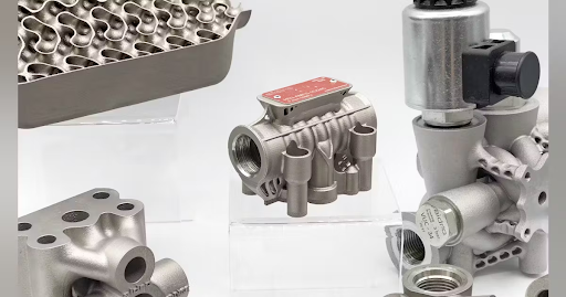
The Power of Consolidation
Traditional design thinking encourages modular assemblies to reduce tooling costs or simplify manufacturing steps. Additive changes the equation. It allows engineers to combine brackets, channels, fastener bosses, or housing components into a single monolithic build.
This isn’t just about aesthetics. Consolidated parts reduce joint failure, eliminate inventory complexity, and simplify post-processing. Features like snap fits, living hinges, and integrated routing can be built directly into the part—without sacrificing structural performance.
Planning for the Inevitable: Post-Processing
No AM part comes off the printer perfectly finished. Cleanup, surface treatment, and even minor machining are often required. Designing with these steps in mind pays dividends. Fragile features should be placed away from support zones. Critical tolerances should include stock for post-machining. Enclosed voids in powder processes must include vent holes for cleaning.
Neglecting post-processing during design often leads to delays, scrap, or rework. As in all manufacturing disciplines, the best way to simplify finishing is to think ahead.
Choosing the Right Material for the Job
Material selection in AM is more complex than pulling a polymer off a chart. The same polymer can behave very differently across processes. Nylon 12 performs well in MJF and SLS, but may exhibit brittleness in certain orientations. TPU offers great flexibility but brings printability challenges. ULTEM™ 9085 brings flame resistance and strength but requires precision thermal control and industrial-level equipment.
Designers must consider chemical exposure, temperature tolerance, and post-processing compatibility when making selections. Data sheets are useful—but only when read in context.
Designing to Prevent Failure
The most common additive failures are also the most predictable: unsupported spans, weak layer adhesion, thermal warping, or unaccounted-for shrinkage. Good DfAM mitigates these by incorporating ribs, gussets, fillets, and gradual transitions.
The earlier failure modes are considered, the fewer surprises surface downstream. A part that breaks during a prototype run costs time. A part that fails in production compromises trust.
Designing for Scale: Build Strategy and Nesting
As AM moves into short-run and full-scale production, throughput becomes critical. How parts are nested in the build chamber, how they’re spaced for airflow, and how they orient relative to others directly impact cycle time and post-processing effort.
Flat orientation reduces build height and speeds turnaround. Strategic nesting in SLS or MJF maximizes part count while balancing powder flow and heat distribution. Clean part access and labeling become essential for high-volume environments.
Designing for a single print is no longer enough. Engineers must think in batches, builds, and workflows.
Final Thoughts: Function Requires Intent
Additive manufacturing has redefined what’s possible. But possibility without intention leads to parts that print—but don’t perform. DfAM isn’t just another acronym; it’s the practical discipline of designing with process realities in mind.
By incorporating these principles early, engineers ensure that their designs are not only printable—but functional, durable, and ready to scale.
Looking to optimize your next design for additive manufacturing?
RapidMade provides engineering-grade 3D printing services and expert DfAM consultation to help your parts succeed in production—not just in the slicer.
Learn more at rapidmade.com or contact info@rapidmade.com to start your project.